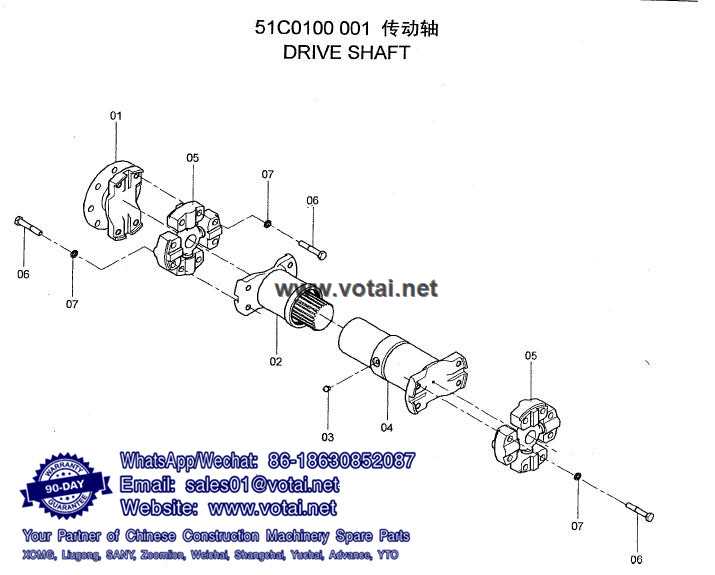
The intricate world of vehicle mechanics is defined by numerous elements that work harmoniously to ensure optimal performance. Each of these components plays a vital role in transferring power and maintaining smooth operation, contributing to the overall efficiency of the machinery.
To truly grasp how these mechanisms function, one must explore the individual segments that comprise the assembly. A thorough examination reveals the relationships and interactions among various elements, showcasing their significance in the system’s design.
In this discussion, we will delve into the essential features and configurations of these components, providing insights into their functionality and how they contribute to the vehicle’s ultimate performance. Understanding these elements not only enhances knowledge but also aids in effective maintenance and troubleshooting.
Understanding Drive Shaft Components
This section explores the essential elements that facilitate the transfer of power in vehicles. Grasping these components is crucial for appreciating how motion is effectively conveyed from one part of the machine to another.
- Transmission: Converts engine output into usable energy.
- Couplings: Connect various sections, allowing for flexibility and alignment.
- Universal Joints: Enable rotation while accommodating angle changes.
- Support Bearings: Stabilize the structure and reduce vibration.
- Flanges: Join different components securely.
Each of these elements plays a pivotal role in the overall functionality and efficiency of the system.
Key Functions of Drive Shaft Parts
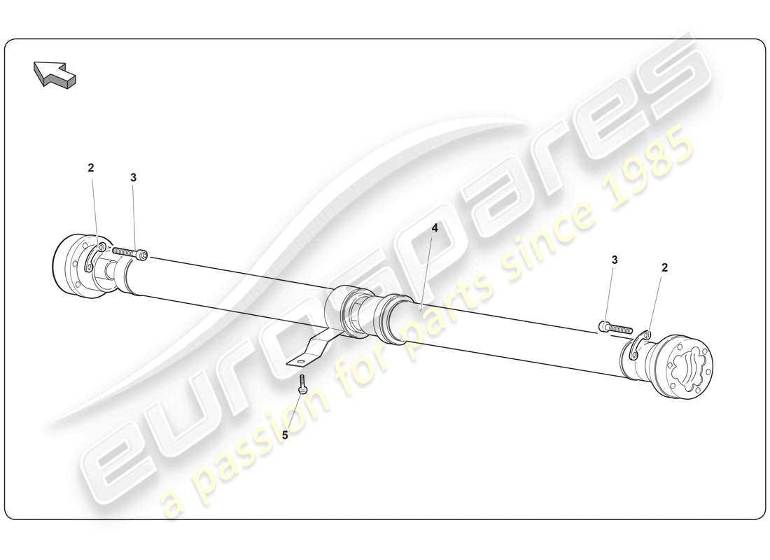
The essential components of a vehicle’s rotational system play a critical role in transferring energy from the engine to the wheels. Their effective interaction ensures smooth motion and efficient power delivery, contributing to overall performance and safety on the road.
Each element in this assembly serves distinct functions that enhance the vehicle’s operational capabilities. Understanding these roles is vital for maintenance and optimization.
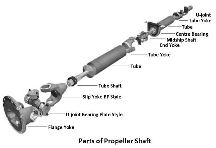
| Component | Function |
|---|---|
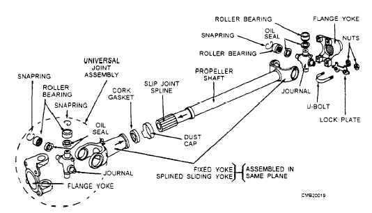
| Universal Joint | Allows for angular movement while transmitting torque, accommodating changes in alignment. |
| Connecting Tube | Transmits rotational motion and supports the structure, ensuring stability under load. |
| Center Bearing | Provides support for longer assemblies, reducing vibration and maintaining alignment. |
| End Yoke | Connects to the transmission and differential, enabling flexible connection points. |
| Slip Joint | Accommodates changes in length due to suspension movement, ensuring continuity of power flow. |
By understanding these functions, vehicle owners and technicians can better appreciate the complexity and importance of this assembly in ensuring reliable and efficient driving experiences.
Common Materials Used in Drive Shafts
The construction of rotational components involves the selection of materials that ensure durability, strength, and resistance to various environmental factors. Understanding the properties of these materials is essential for achieving optimal performance in mechanical applications.
| Material | Properties | Applications |
|---|---|---|
| Steel | High tensile strength, good fatigue resistance | Standard applications in automotive and industrial machinery |
| Aluminum | Lightweight, corrosion-resistant, good machinability | Used in lightweight vehicles and high-performance applications |
| Composite Materials | High strength-to-weight ratio, customizable properties | Advanced applications in aerospace and motorsports |
| Carbon Fiber | Exceptional stiffness, low weight, high resistance to deformation | Specialized high-performance scenarios and luxury vehicles |
| Cast Iron | Excellent wear resistance, good vibration damping | Heavy machinery and applications requiring durability |
Choosing the appropriate material is crucial for ensuring the efficiency and reliability of mechanical systems. Each type offers unique advantages that cater to specific operational demands.
How to Read Drive Shaft Diagrams
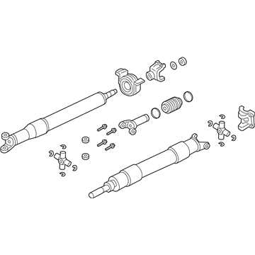
Understanding visual representations of mechanical components is crucial for effective maintenance and troubleshooting. These illustrations serve as a roadmap, guiding users through the various elements and their interconnections. Familiarity with the symbols and notations used can significantly enhance comprehension and facilitate informed decision-making.
To effectively interpret these visuals, one should start by identifying the key components depicted. Each element is typically labeled, providing insight into its function and relationship with other parts. It is essential to pay attention to the scales and dimensions, as they indicate the size and placement of the components within the assembly.
| Symbol | Description |
|---|---|
| ⬤ | Connection point |
| ↔ | Movement direction |
| ⚙ | Gear or cog mechanism |
| ⌀ | Circular component |
Additionally, understanding the flow of forces and motions depicted in these images can aid in grasping how the entire system operates. By focusing on how the elements interact with one another, one can better anticipate potential issues and improve overall efficiency.
Typical Issues with Drive Shaft Assemblies
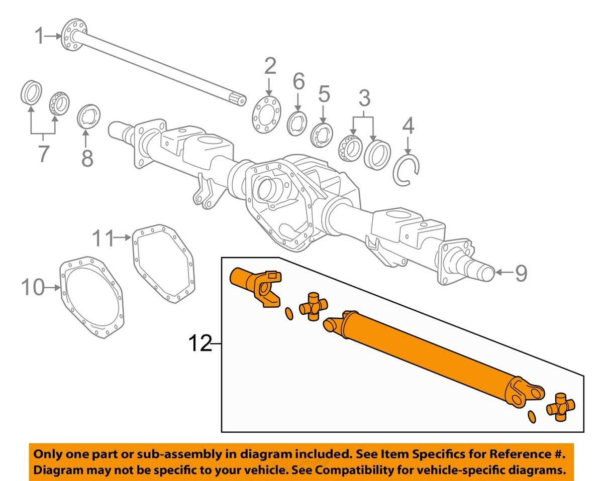
Assemblies that transfer rotational motion often encounter several common problems, affecting their overall performance and reliability. Understanding these issues can help in timely diagnosis and maintenance, ensuring smoother operation and longevity.
Vibration and Noise
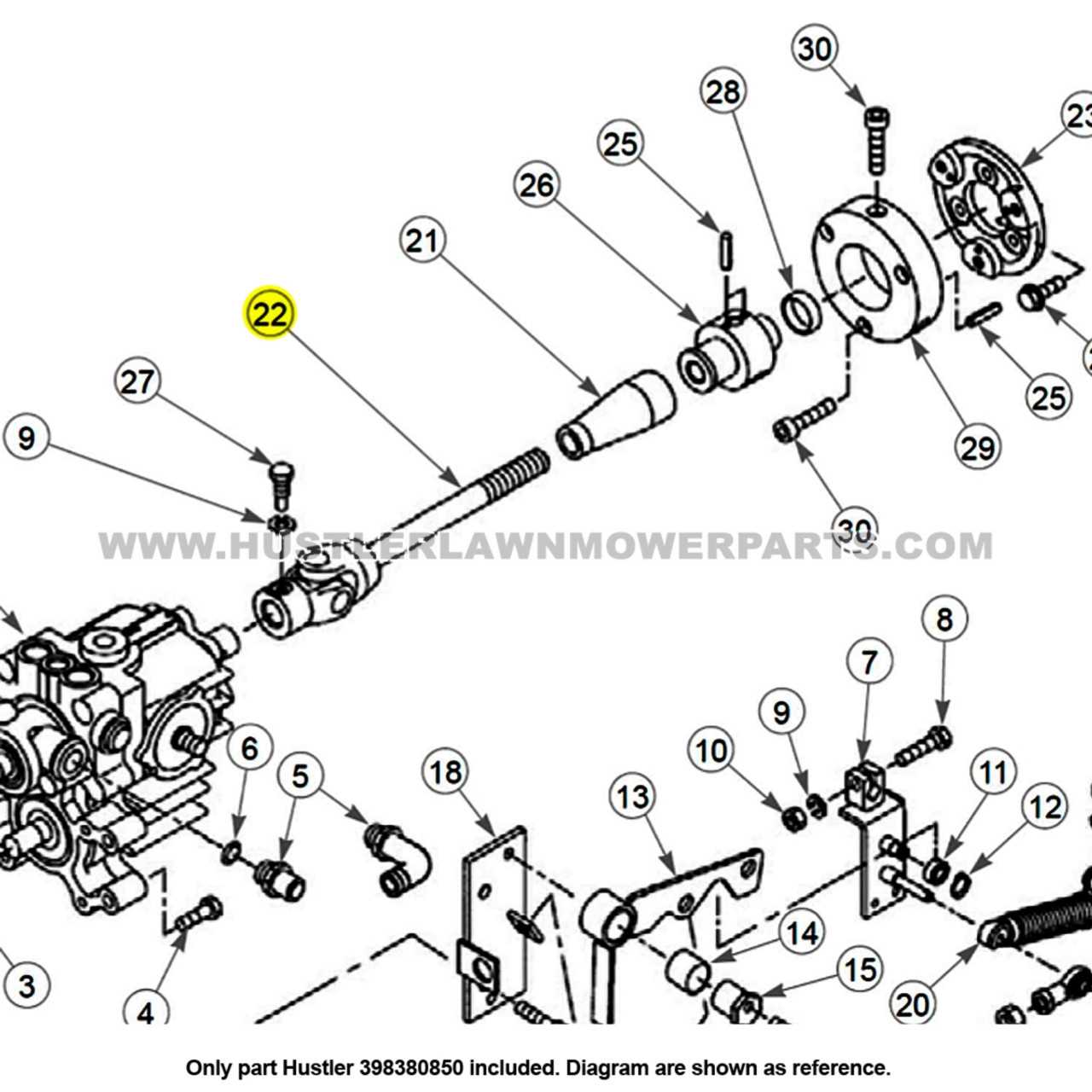
Excessive vibration and noise can indicate imbalance or misalignment within the system. These symptoms not only lead to discomfort during operation but can also result in accelerated wear of surrounding components.
Wear and Tear
Over time, the components within these assemblies may experience significant wear. This can manifest as cracks or deterioration, often necessitating replacement to prevent complete failure and ensure optimal functionality.
Maintenance Tips for Drive Shaft Longevity
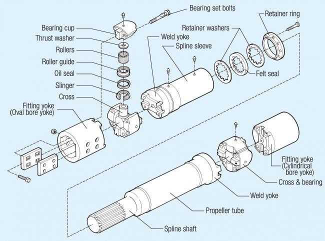
Ensuring the durability of key components in your vehicle involves regular attention and care. By implementing effective maintenance practices, you can significantly extend their lifespan and enhance overall performance.
Regular Inspections
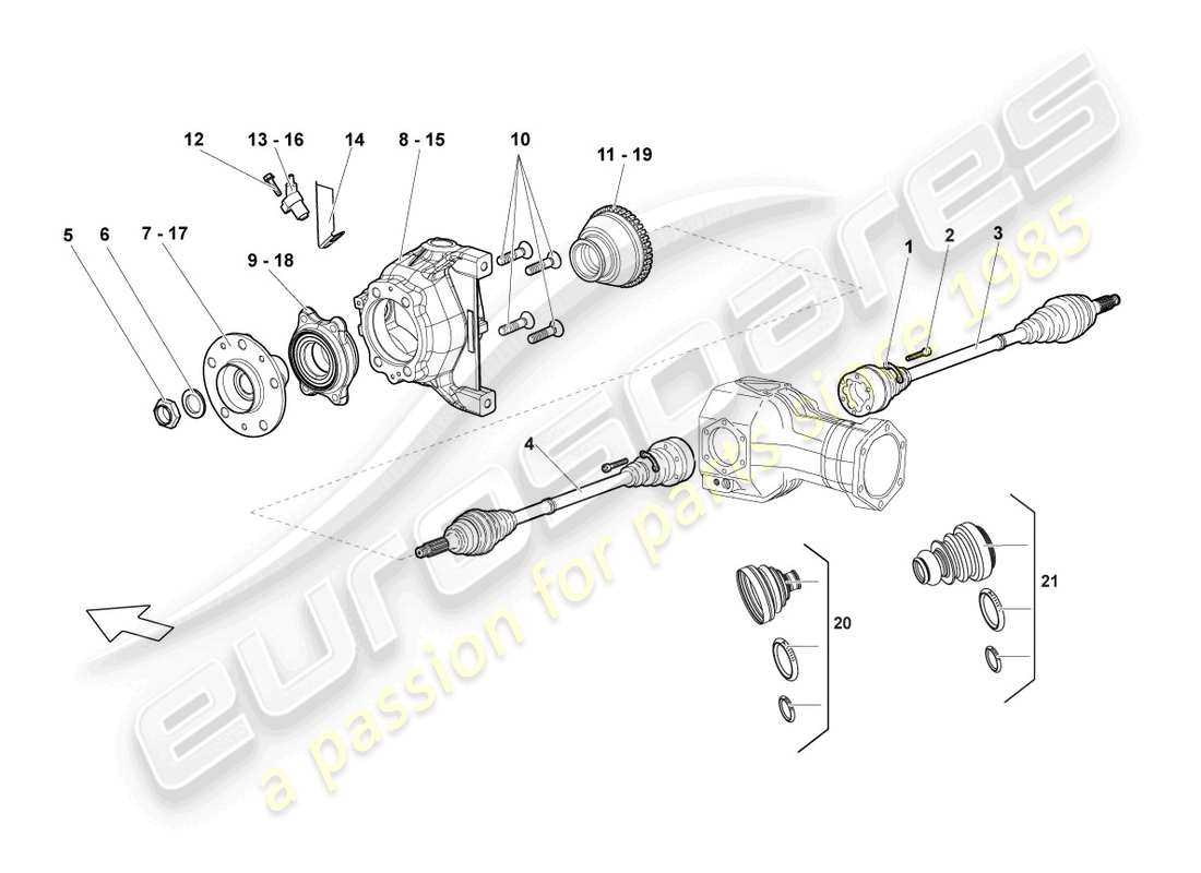
Frequent examinations are essential. Look for signs of wear or damage, such as cracks or excessive rust. Early detection allows for timely repairs, preventing further issues.
Lubrication and Cleaning
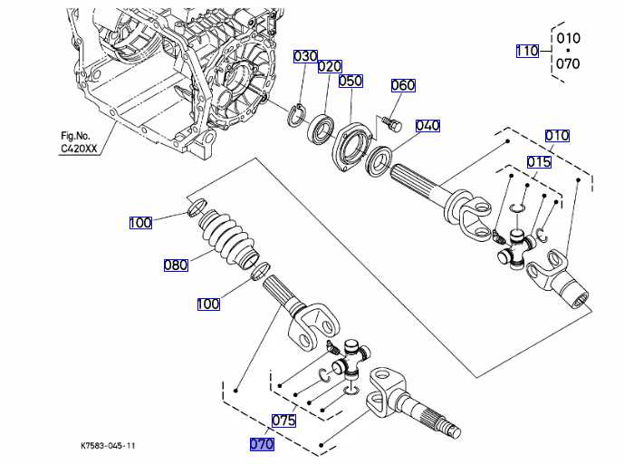
Proper lubrication minimizes friction and wear. Use high-quality grease and ensure all necessary areas are serviced regularly. Additionally, clean any accumulated dirt or debris to maintain optimal function.
Comparing Solid vs. Hollow Drive Shafts
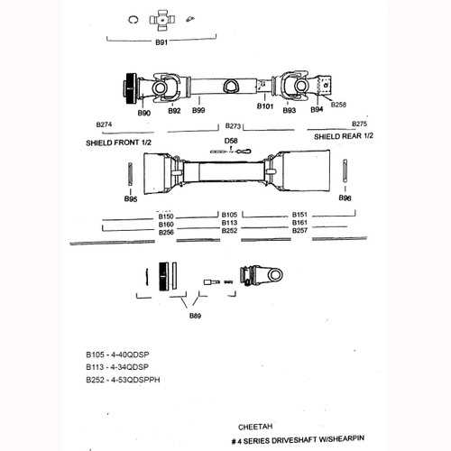
When evaluating different types of rotational components used in machinery, it’s essential to understand the benefits and drawbacks of each design. The choice between a compact and a tubular variant can significantly impact performance, weight, and durability. Analyzing these differences helps in selecting the most suitable option for specific applications.
Compact Designs: The solid variant typically offers greater strength and resistance to torsional stress. This structure is often preferred in situations where durability is critical, as it can withstand higher loads without deformation. Additionally, a solid configuration may simplify manufacturing processes, leading to potential cost savings.
Tubular Structures: On the other hand, the hollow design is generally lighter, which can enhance efficiency, especially in high-speed applications. The reduced weight helps in minimizing inertia, allowing for quicker acceleration and deceleration. Furthermore, the internal space can be utilized for other purposes, such as housing sensors or cables, providing additional functional benefits.
Ultimately, the decision between these two configurations depends on specific performance requirements, including load-bearing capacity, weight constraints, and application scenarios. Understanding these characteristics will lead to more informed choices and improved overall efficiency in mechanical systems.
Importance of Proper Alignment in Drive Shafts
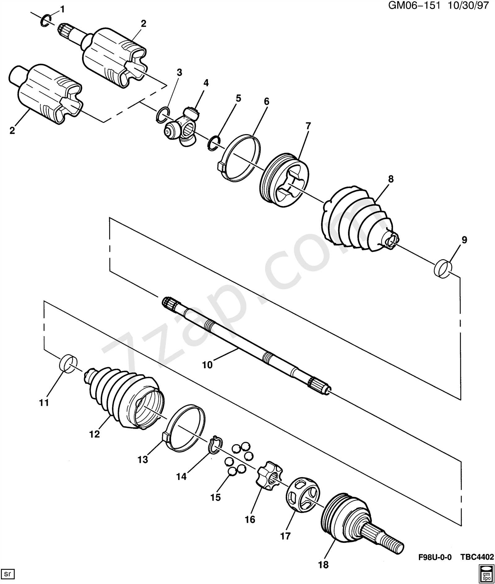
Ensuring the correct positioning and orientation of rotational components is crucial for optimal performance and longevity of any mechanical system. Misalignment can lead to various issues that affect efficiency, reliability, and safety. Understanding the significance of precise alignment helps in maintaining smooth operation and reducing wear and tear.
Consequences of Misalignment
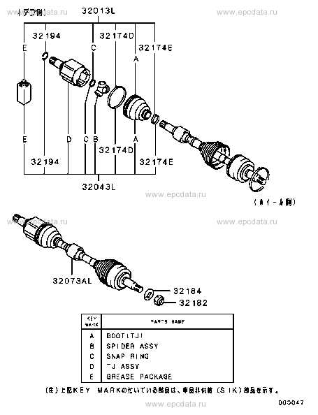
Improper positioning can result in several negative outcomes, including:
- Increased vibration, leading to discomfort and potential damage.
- Premature wear of bearings and other connected elements.
- Reduced energy efficiency, causing higher operational costs.
- Potential for catastrophic failure, risking safety and costly repairs.
Benefits of Correct Orientation
Maintaining accurate alignment offers numerous advantages:
- Enhanced overall performance and reliability.
- Extended lifespan of mechanical components.
- Improved fuel efficiency and reduced emissions.
- Minimized maintenance costs and downtime.
In summary, paying attention to the alignment of rotational systems is essential for ensuring effective functionality and preventing significant mechanical failures. Regular checks and adjustments can significantly improve the operational health of the machinery involved.