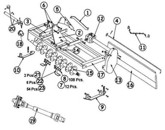
Maintaining and repairing agricultural machinery often requires a clear understanding of how various elements of the equipment are arranged. Having access to detailed visual representations can significantly simplify the process of identifying specific components and their connections. This section provides insight into the general layout of important mechanisms used in farm tools.
Each piece of machinery consists of numerous interconnected parts that work together to perform specific functions. In this guide, you’ll find explanations that help identify key elements involved in the operation of such tools. A well-structured layout allows users to pinpoint components, ensuring smoother maintenance and replacement processes.
Exploring this information will equip you with the necessary knowledge to handle mechanical issues effectively, ensuring long-term efficiency and performance. This overview aims to simplify the understanding of how these tools are structured.
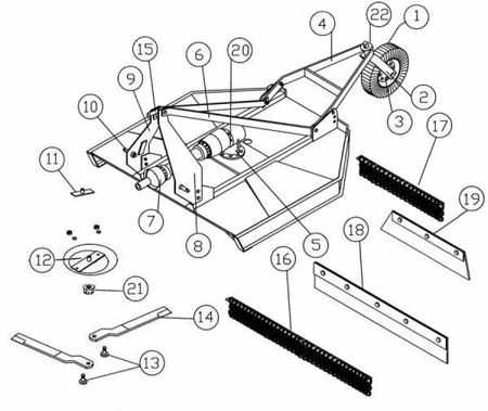
County Line Rotary Cutter Components Overview

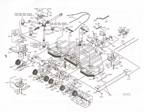
Understanding the essential elements of this type of agricultural tool is crucial for efficient operation and maintenance. Each component plays a significant role in ensuring the equipment works smoothly and delivers optimal performance. By familiarizing yourself with the main mechanical elements, you can better troubleshoot issues and ensure the device stays in top condition.
Frame and Structural Support: The backbone of the machine, this element provides the stability needed to handle tough tasks. It ensures the equipment can endure the strain of heavy use in the field.
Gearbox Assembly: A vital element responsible for transferring power from the engine to the working mechanism. Proper maintenance of this component is essential for long-lasting performance and efficiency.
Blades: The cutting elements are designed to manage thick vegetation and other obstacles. These need regular inspection to maintain sharpness and effectiveness in fieldwork.
Driveline: Connecting the power source to the functional elements, this part ensures the smooth transmission of energy. Ensuring its proper alignment and lubrication is key to preventing breakd
Main Frame Structure and Design
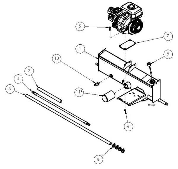
The foundation of any agricultural machinery is the durability and effectiveness of its core structure. This section focuses on the key design principles that ensure stability, functionality, and long-term performance. The main framework serves as the backbone, providing the necessary support for all operational components, enabling them to withstand various forces during use.
Robustness and Durability
One of the primary considerations in designing the frame is its ability to endure stress and resist wear over time. The materials used in construction are carefully selected for their strength and resilience, ensuring that the frame can handle the demands of heavy-duty tasks without compromising structural integrity.
Design Efficiency
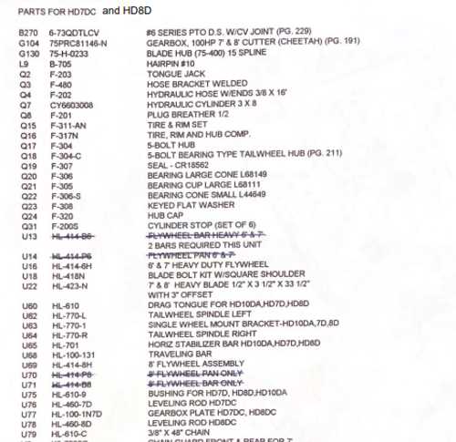
Efficiency in design is equally important to ensure that all mechanical components work harmoniously. Proper alignment, weight distribution, and reinforcements are integrated into the design to maximize performance while minimizing the risk of damage or malfunction. A well-engineered structure not only enhances the machinery’s reliability but also prolongs its lifespan.
Blade Assembly and Cutting Mechanism
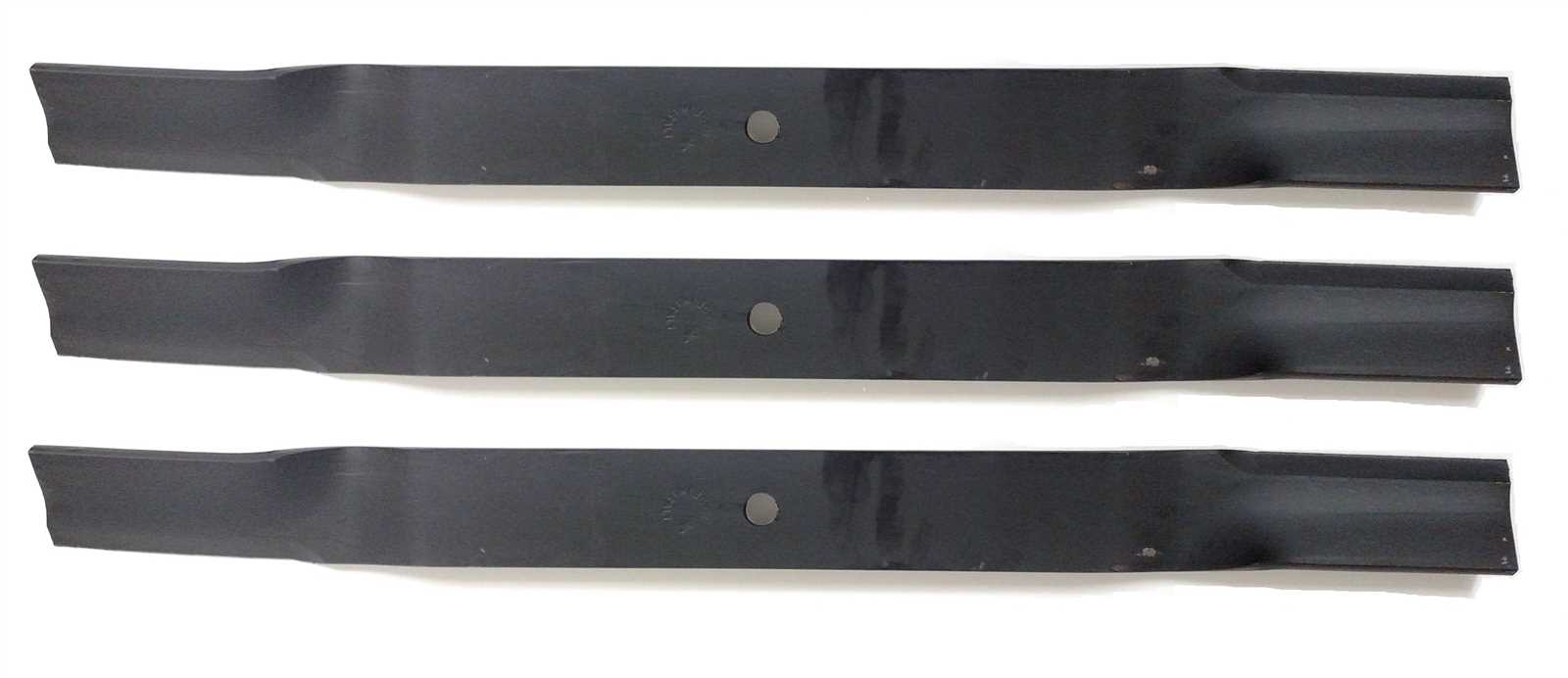
The blade assembly is the core component responsible for effective vegetation trimming. It is designed to create precise cuts, ensuring consistent and efficient performance. The cutting mechanism, which operates in conjunction with the blade, plays a crucial role in determining the quality of the trimming process. Through a balanced design and optimized movement, these parts work seamlessly to deliver smooth operation, minimizing resistance and maximizing sharpness. The synchronization of these elements ensures that the overall system functions reliably, providing high-quality results with every use.
Sharpness and balance are key to ensuring the blade maintains its cutting edge over time. By maintaining the correct alignment and avoiding unnecessary wear, the cutting system remains effective in handling a wide range of vegetation types. The mechanism also incorporates safety features, protecting the user and equipment from potential damage or accidents caused by debris or improper operation.
Gearbox Functions and Specifications
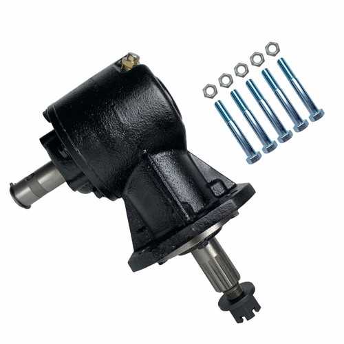
The gearbox is a crucial component designed to manage the transfer of mechanical power within the equipment. It is responsible for adjusting the speed and torque to meet the specific operational demands, ensuring the machinery runs smoothly and efficiently. Understanding its role and key specifications can help in maintaining optimal performance.
Main Functions of the Gearbox
- Power Transmission: Transfers energy from the engine to the working components, converting rotational motion into usable force.
- Speed Adjustment: Regulates the speed by controlling the gear ratios, which allows for flexible operation under varying conditions.
- Torque Control: Enhances or reduces torque as needed, ensuring appropriate force is applied to achieve the desired results.
Key Specifications
- Gear Ratio: Determines the relationship between input and output speeds, affecting the
Driveline Parts and Maintenance Tips
The driveline is a crucial component in agricultural machinery, ensuring power transfer from the tractor to various implements. Proper upkeep and attention to key elements can significantly extend the lifespan of your equipment, preventing unexpected downtime and costly repairs. Below are essential tips to keep the driveline running smoothly and efficiently.
Component Maintenance Tip Universal Joints Regularly inspect for wear and ensure they are properly lubricated to prevent friction and avoid excessive vibrations. Driveshaft Check for any bends or misalignments, and ensure the shaft is clean and free of debris before each use to maintain smooth operation. Hitch and Mounting Connections
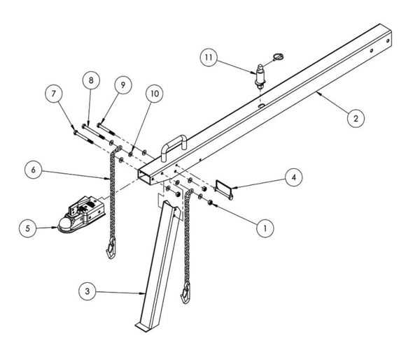
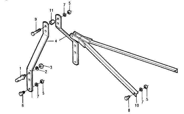
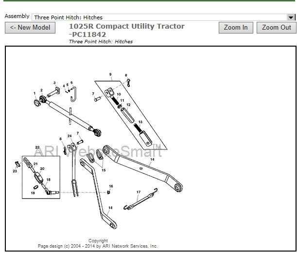
The integration of towing systems and attachment fittings plays a crucial role in ensuring efficient operation and stability during use. Proper connections enhance the performance of agricultural implements, allowing for seamless interaction with various machinery.
When considering the assembly of these systems, it is essential to examine the types of hitches available. Common options include fixed and adjustable hitches, which cater to different operational needs. Each hitch type offers unique benefits, providing flexibility and ease of attachment.
Mounting brackets are vital components that ensure secure connections between equipment and tractors. They come in various shapes and sizes, allowing for compatibility with a range of implements. Understanding the specifications of these brackets is important for maintaining safety and efficiency during operation.
In addition, regular inspection of connections is necessary to identify wear or damage. Ensuring that all components are in optimal condition contributes to reliable performance and extends the lifespan of the machinery.
Skid Shoes and Ground Clearance Adjustment
The adjustment of sliding components and ground height is crucial for maintaining optimal performance and ensuring even cutting. Properly configured skid shoes play a significant role in enhancing maneuverability and preventing damage to the surface being treated.
Adjusting the skid shoes involves a few key steps:
- Inspect the current positioning of the skid shoes for wear and tear.
- Determine the desired ground clearance based on the specific terrain and intended use.
- Loosen the mounting bolts to allow for height adjustments.
- Raise or lower the skid shoes to achieve the preferred clearance.
- Tighten the bolts securely to ensure stability during operation.
Maintaining the appropriate ground clearance not only prolongs the lifespan of the equipment but also improves cutting efficiency. Regular checks and adjustments should be part of routine maintenance to ensure optimal results.
Safety Shields and Guards Placement
Proper positioning of protective barriers is essential for ensuring safety during operation. These components are designed to minimize the risk of injury by preventing access to moving parts and containing debris. It is crucial to follow manufacturer recommendations for the installation and maintenance of these safety features.
First and foremost, ensure that all shields are securely fastened and free from damage. Regular inspections should be conducted to identify any signs of wear or misalignment. Proper placement not only enhances user safety but also optimizes the equipment’s performance.
Additionally, it is important to consider the working environment. Obstacles and uneven terrain can impact the effectiveness of safety guards. Therefore, adjustments may be necessary to maintain proper coverage, particularly in challenging conditions. Taking the time to evaluate and enhance safety shield placement can lead to a more secure and efficient operation.
Replacement Parts for Wear and Tear
Maintaining machinery in optimal condition is essential for its longevity and performance. Over time, certain components may experience degradation due to regular use. It is crucial to identify these elements and replace them promptly to ensure smooth operation and avoid further damage.
Common Components Prone to Damage
- Blades: Frequent exposure to various materials can dull or chip the cutting edges.
- Belts: These can wear down from constant tension and movement, affecting efficiency.
- Bearings: As friction increases, these parts may develop noise or vibration issues.
- Seals: Over time, seals can crack or harden, leading to potential leaks.
Tips for Identifying Replacement Needs
- Regular Inspections: Schedule frequent checks to assess the condition of key components.
- Listen for Unusual Sounds: Grinding or squeaking noises can indicate worn parts.
- Monitor Performance: A decline in efficiency may signal the need for replacements.
- Check for Visible Damage: Look for signs of wear, such as fraying or cracks.