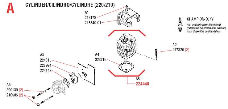
When it comes to maintaining and repairing various mechanical devices, having a clear representation of the inner workings is invaluable. Visual guides offer a comprehensive view of individual elements and their connections, making it easier to identify what needs attention and how components interact. Such illustrations are essential tools for anyone looking to keep equipment in optimal condition.
Detailed illustrations of machine structures allow users to pinpoint specific elements, ensuring precise and efficient repairs. These resources help in understanding not just the arrangement, but also the function of each piece within the overall system. This clarity can significantly reduce time spent on troubleshooting and improve the accuracy of maintenance tasks.
Using these schematics, users can easily navigate through complex assemblies, locate the required elements, and ensure each step of the repair process is executed correctly. This makes them especially valuable for technicians and enthusiasts who aim to achieve professional results when servicing their equipment.
Country Clipper Parts Diagram
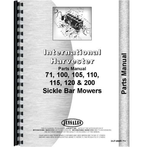
Understanding the layout of different components is essential for proper maintenance and troubleshooting. A visual guide can help pinpoint the exact location of each element, making it easier to identify and address any issues that arise. Knowing how each piece fits into the system allows for quicker repairs and ensures smoother operation over time.
Component Arrangement Overview
The arrangement of various elements is strategically designed to optimize functionality. Each section plays a specific role in the overall system, and understanding their placement can aid in diagnosing problems. The visual guide serves as a valuable tool for anyone looking to improve their understanding of the equipment’s structure.
Benefits of a Visual Guide
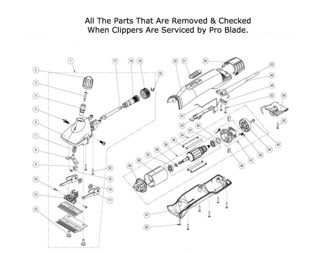
A detailed visual representation not only helps in locating specific elements but also assists in planning maintenance tasks. It allows for a more systematic approach when servicing or replacing individual components, reducing downtime and
Understanding the Diagram Layout
When exploring the layout, it is important to grasp how the illustration provides a visual guide to the different elements. Each section within the layout is designed to help users quickly identify various components and their positions. This organization makes it easier to understand how everything fits together and functions as a whole.
The layout usually consists of distinct sections, each serving a specific purpose. Here’s a closer look at the typical arrangement:
- Main Assemblies: These represent the larger structures and are usually depicted prominently, showing how the primary elements connect.
- Key Components and Their Functions
Understanding the various elements and their roles is crucial for maintaining optimal performance and ensuring smooth operation. Each part plays a specific role, contributing to the overall efficiency and durability of the equipment.
- Engine: Powers the entire system, providing the necessary force to operate the cutting mechanism and other moving parts.
- Cutting Deck: Houses the blades and is responsible for directing grass clippings away from the blades, ensuring a clean and consistent cut.
- Blades: Rotate rapidly to trim the grass to the desired length, requiring regular sharpening for optimal results.
- Examine the overall layout to gain a comprehensive view.
- Focus on specific sections to understand their functions.
- Note any areas that show signs of wear or require replacement.
How to Identify Part Numbers
Finding the right replacement components for a device or machinery can be simplified by understanding how to recognize part numbers. Each code serves as a unique identifier that provides valuable information about the component’s specifications, making it easier to match it with the correct item.
Decoding the Numbering System
Part numbers often follow a structured format, which may include details such as the type of component, size, material, or manufacturing date. Learning to interpret this structure can help in locating the appropriate item. The sequence of characters may include a combination of letters and digits, where each segment represents different attributes.
Using a Reference Table
A reference table can assist in decoding and understanding what each section of the number signifies. Below is an example that demonstrates typical sections of a part
Locating Specific Parts Quickly
Finding the right components in a complex system can often be challenging. Having a clear strategy to identify what you need without wasting time is crucial. Knowing how to navigate through various resources and understanding key reference points can significantly speed up the process.
Utilize Available Resources Efficiently
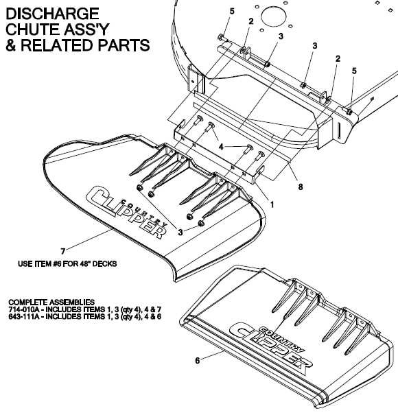
Make sure to take advantage of all resources at your disposal, such as online manuals, user guides, and maintenance tools. These can offer valuable information for pinpointing the exact item you need. When using these resources, focus on cross-referencing key details like model numbers, dimensions, or unique identifiers to ensure a quicker match.
Leverage Visual Aids and Illustrations
Visual aids, such as illustrations or exploded views, are extremely helpful for quick identification. These visuals provide a clear overview of each component’s location
Using the Diagram for Maintenance
Utilizing a visual reference for upkeep is essential for ensuring the longevity and efficiency of equipment. This reference provides valuable insights into various components and their relationships, making maintenance tasks more straightforward. Understanding the layout can help operators identify parts that require attention and ensure that every element functions harmoniously.
Identifying Components
A clear representation allows users to easily spot individual elements. Familiarizing oneself with these components is crucial for effective maintenance. Consider the following steps:
Planning Maintenance Tasks
Once the elements are identified, planning maintenance becomes more efficient. Here are some suggestions to enhance your upkeep routine:
- Create a checklist based on the visual reference.
- Schedule regular inspections for high-wear components.
- Keep a record of any repairs or replacements for future reference.
Tips for Ordering Replacement Parts
When it comes to acquiring components for machinery maintenance, ensuring a seamless process is crucial. Properly sourcing these elements not only prolongs the lifespan of your equipment but also enhances its performance. Here are some key suggestions to consider when placing an order for necessary replacements.
Identify the Specific Component
Before making any purchases, it is essential to determine the exact item required for your equipment. Referencing the manual or any available schematics can significantly aid in identifying the correct element. This step minimizes the risk of ordering incorrect items, which can lead to frustration and unnecessary delays.
Utilize Reputable Suppliers
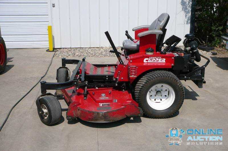
Selecting reliable vendors is vital for obtaining quality replacements. Look for suppliers with positive customer reviews and a solid reputation in the industry. This ensures that the components are genuine and meet the necessary standards, providing peace of mind for your maintenance needs.
Common Issues and Diagram Solutions
Understanding the typical challenges that can arise with equipment is essential for effective maintenance and repair. Identifying these common problems enables users to approach solutions more systematically, often using visual aids to enhance clarity and comprehension. By addressing these frequent complications, users can improve the overall performance and longevity of their machinery.
One prevalent issue involves the malfunctioning of cutting mechanisms. This can often result from dull blades or improper alignment. To resolve this, it is crucial to regularly check the sharpness of the blades and adjust their positioning as necessary. A well-illustrated reference can help in ensuring that all components are correctly aligned.
Another frequent concern is engine overheating. This can stem from inadequate lubrication or blocked cooling systems. Users should refer to maintenance guides that depict the lubrication points and cooling pathways, allowing them to perform regular checks and cleaning. Timely intervention can prevent severe damage and extend the machinery’s operational life.
Lastly, vibrations during operation can indicate loose parts or imbalances within the structure. Utilizing visual references can assist in pinpointing potential areas of concern, allowing for adjustments to be made effectively. Ensuring that all components are securely fastened can significantly reduce operational disturbances.
Upgrading Parts with the Diagram
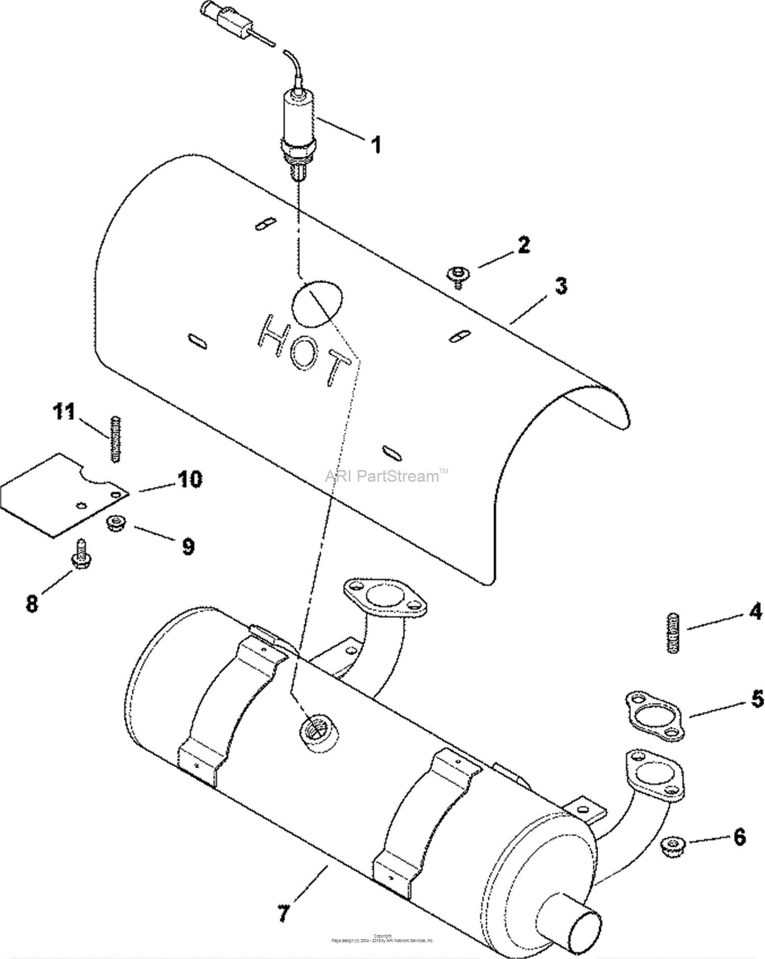
Enhancing the functionality of your equipment often requires a detailed understanding of its components. Utilizing a visual representation can greatly assist in identifying the necessary upgrades for improved performance. This guide aims to illustrate how to effectively implement enhancements by referencing such illustrations, ensuring a seamless process.
When considering upgrades, it is essential to evaluate the existing elements and determine which ones could benefit from replacement or enhancement. The following table outlines key components and potential upgrades to enhance overall efficiency.
Component Recommended Upgrade Benefits Engine High-efficiency model Improved power output and fuel efficiency Blades Enhanced cutting blades Sharper edges for a cleaner cut Transmission Upgraded transmission system Smoother operation and better speed control Frame Reinforced structure Increased durability and stability Wheels All-terrain tires Improved traction and mobility By following the guidance provided in these illustrations, you can strategically upgrade your equipment, leading to enhanced efficiency and performance. Regular assessments and updates based on these visual aids can significantly extend the lifespan of your machinery.