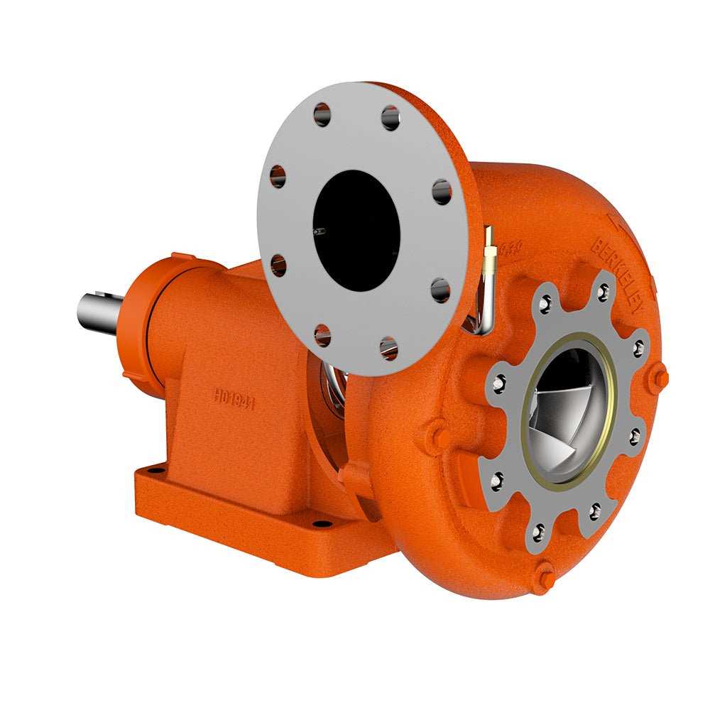
When it comes to high-performance fluid handling systems, the intricate design and assembly of individual elements are crucial for optimal functionality. Every system consists of a variety of interconnected modules that work in harmony to ensure efficient flow, pressure control, and longevity. Knowing how these components interact, as well as understanding their specific roles, can greatly enhance maintenance and troubleshooting efforts.
To better comprehend the structure of these mechanisms, it’s essential to have a clear representation of how the various segments fit together. An in-depth visual guide to these interconnected elements can provide a clear overview of their function and placement within the system. Such a reference is invaluable for technicians, engineers, and operators alike, enabling them to identify potential issues and ensure smooth operation.
With the right set of instructions, assembling or repairing such complex systems becomes more manageable. This guide will explore the key components, their arrangement, and the necessary tools for effective operation, allowing users to navigate the technical landscape with confidence.
Understanding Berkeley Pump Components
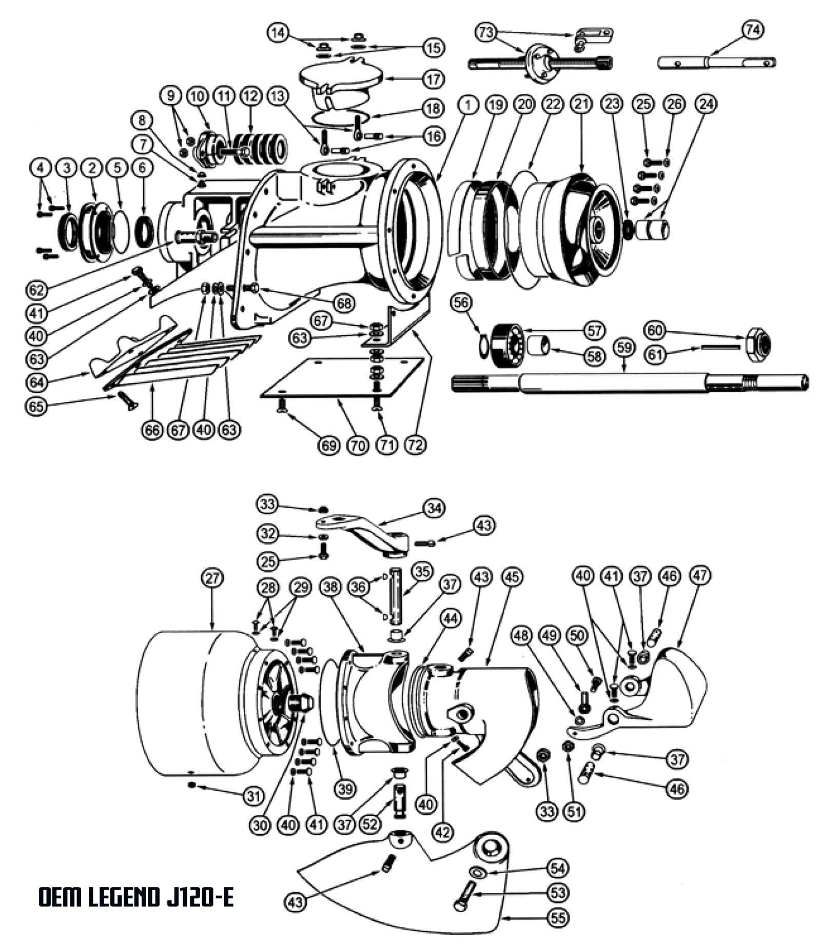
Gaining insight into the essential elements of a fluid movement system is crucial for effective operation and maintenance. Each component plays a vital role, contributing to the overall efficiency and performance of the mechanism. By familiarizing oneself with these integral parts, one can enhance both functionality and longevity.
Key Elements of the System
The primary components include the driving mechanism, which provides power, and the housing that protects internal parts. Additionally, the flow channels are designed to optimize the movement of liquids, ensuring minimal resistance. Understanding these elements can significantly impact operational success.
Maintenance and Troubleshooting
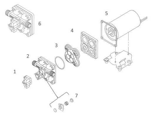
Regular inspection and timely replacement of worn components are essential for sustaining performance. Identifying common issues, such as leaks or inefficiencies, can prevent larger failures. Proper care extends the system’s lifespan and enhances its ultimate effectiveness.
How Berkeley Pump Diagrams Improve Maintenance
Effective visual representations play a crucial role in enhancing the upkeep of mechanical systems. By providing clear illustrations, technicians can easily identify components and their functions, leading to quicker troubleshooting and repairs. This streamlined approach ultimately reduces downtime and extends the lifespan of equipment.
Facilitating Quick Identification
Visual aids allow maintenance personnel to swiftly recognize each element within the assembly. This clarity minimizes confusion and accelerates the diagnostic process, enabling more efficient service.
Streamlining Communication
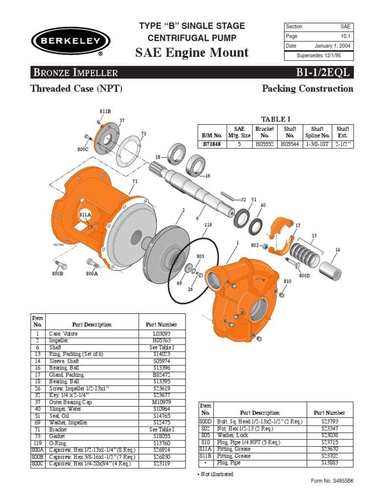
Utilizing detailed visuals fosters better collaboration among team members. When everyone references the same schematic, it enhances understanding and ensures accurate information exchange during maintenance discussions.
| Benefit | Description |
|---|---|
| Efficiency | Reduces time spent on identifying issues. |
| Accuracy | Improves precision in repairs and replacements. |
| Collaboration | Enhances team communication and understanding. |
Key Features of a Berkeley Pump Diagram
This section highlights the essential attributes of a schematic representation that illustrates the intricate components and their interconnections within a specific fluid-moving system. Understanding these features is crucial for both maintenance and operational efficiency.
Essential Components
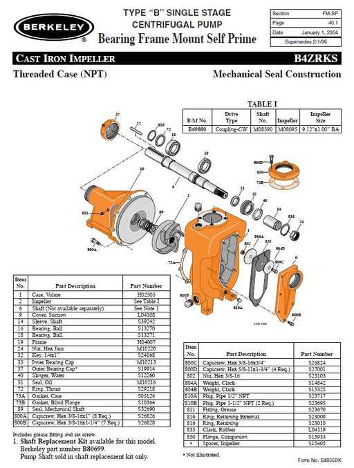
- Intake and discharge mechanisms
- Impeller design and configuration
- Sealing and bearing arrangements
- Drive assembly details
Functional Attributes
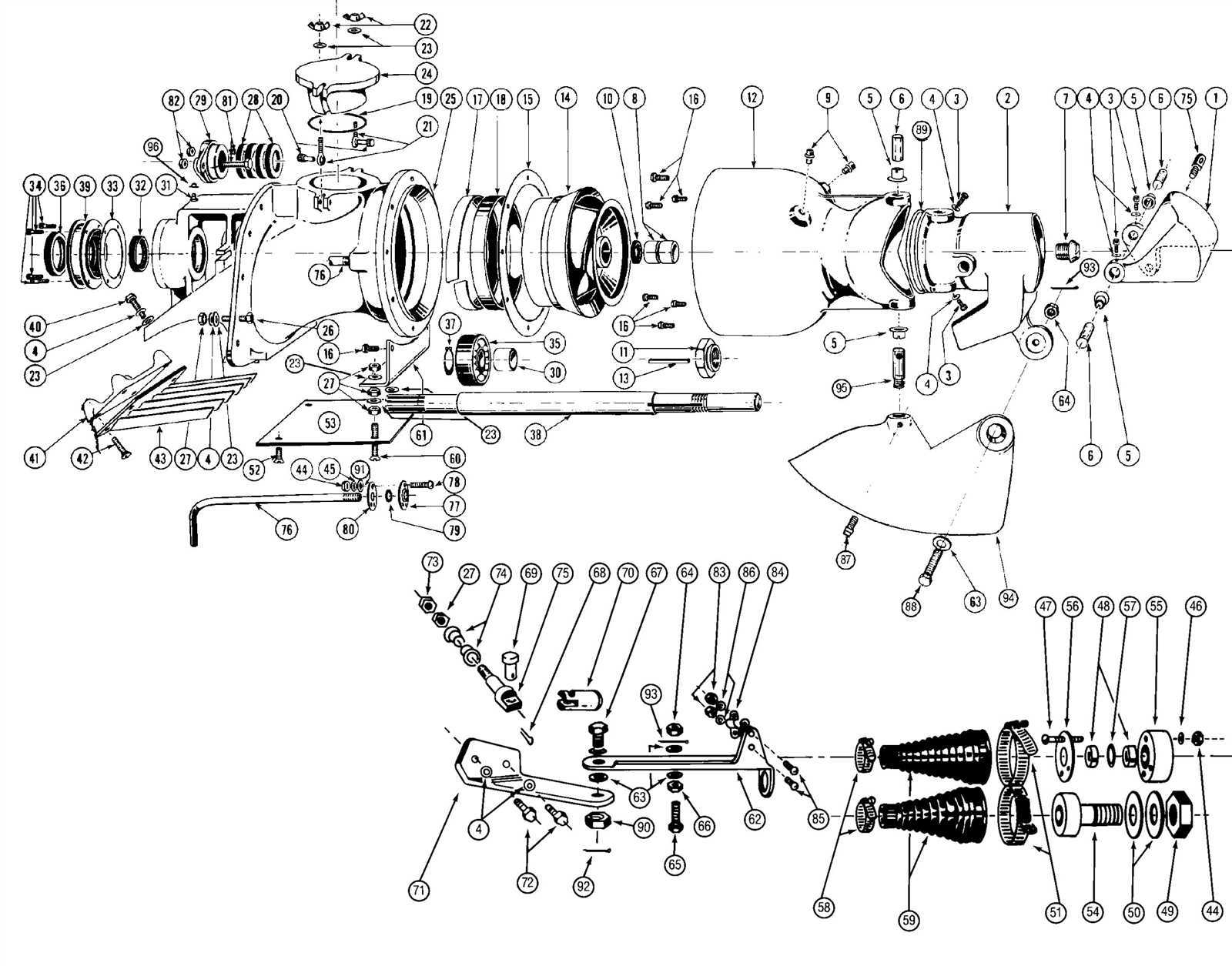
- Clear labeling of each element for easy identification
- Logical flow representation for enhanced understanding
- Compatibility indicators for component integration
- Maintenance and troubleshooting pointers
Identifying Pump Parts for Efficient Repairs
Understanding the components of a fluid transfer device is crucial for effective maintenance and troubleshooting. By familiarizing oneself with the various elements, one can quickly identify issues and ensure optimal performance. This knowledge empowers operators to carry out repairs with confidence and precision.
Key Components to Recognize
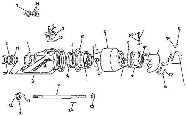
- Impeller: This rotating element is responsible for moving fluid through the system.
- Casing: The outer shell that contains and directs the flow of the liquid.
- Shaft: The central rod that connects the motor to the impeller, facilitating rotation.
- Seals: These components prevent leaks by creating a barrier between moving parts.
- Bearings: Support the shaft and reduce friction during operation.
Steps for Efficient Troubleshooting
- Conduct a visual inspection to identify any obvious damage or wear.
- Check the seals for leaks, as these are common failure points.
- Examine the bearings for any signs of overheating or noise.
- Assess the alignment of the shaft to ensure smooth operation.
- Refer to schematics or manuals for detailed information on each component.
By systematically identifying and understanding each element, operators can enhance their maintenance practices and extend the lifespan of their equipment.
How to Read a Berkeley Pump Blueprint
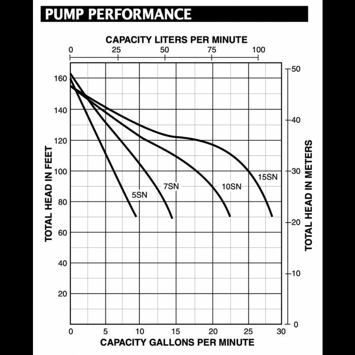
Understanding the technical schematics of a mechanical system is essential for ensuring proper assembly, maintenance, and troubleshooting. These visual representations provide a detailed overview of how individual components fit together, highlighting key dimensions, materials, and operational relationships. Interpreting these drawings accurately allows for efficient work and prevents errors during installation or repair tasks.
Key Elements of a Technical Drawing

A typical blueprint will feature a variety of symbols, numbers, and annotations that give insight into how each component interacts with the others. These symbols often represent physical elements such as housing, impellers, or seals. Dimensions and tolerances are crucial, providing the exact measurements for fabrication and assembly. An understanding of these elements is fundamental when working with any mechanical system.
Understanding the Symbols and Measurements
Each blueprint will contain a set of standardized symbols that correspond to different types of mechanical components. Familiarity with these symbols is essential for correctly interpreting the document. Additionally, measurements such as diameter, length, and pressure ratings will be specified, allowing engineers and technicians to assess compatibility and performance.
| Component | Symbol | Measurement |
|---|---|---|
| Impeller | Diameter: 200 mm | |
| Housing | Length: 300 mm | |
| Seal | Pressure rating: 10 bar |
By carefully examining these drawings, one can ensure all components align properly and function as intended within the system. Whether you are building from scratch or repairing an existing unit, accurate interpretation of these documents is crucial for success.
Common Issues Highlighted in Pump Diagrams
Technical illustrations often provide valuable insights into the components and functionality of mechanical systems. They help identify potential trouble spots that may arise during operation. By analyzing these visuals, users can better understand where failures tend to occur, allowing for more efficient troubleshooting and maintenance. Certain patterns of wear, stress, and other operational challenges frequently appear, offering clues about the system’s long-term durability and performance.
Wear and Tear on Key Components
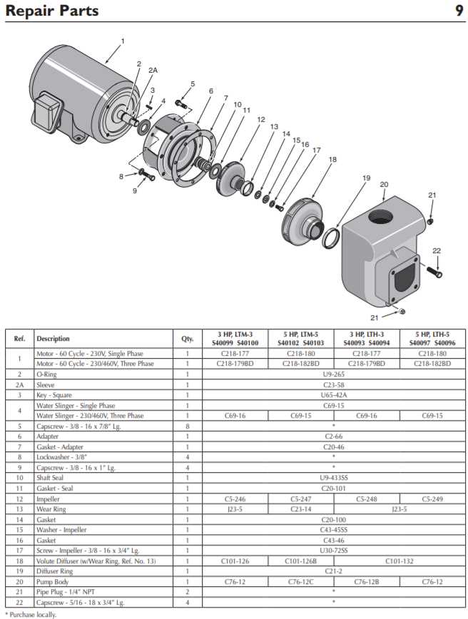
One of the most common issues illustrated in such technical schematics is the wear on critical elements. Over time, parts subjected to continuous motion or pressure can degrade, leading to reduced efficiency and eventual failure. These components may include seals, bearings, and other moving elements, all of which experience friction and fatigue during regular use. Regular inspection and early replacement of these elements can significantly extend the overall lifespan of the system.
Misalignment and Improper Assembly
Another frequent concern is misalignment within the mechanical system. When components are not properly aligned, it can lead to uneven wear, increased vibration, and a host of operational issues. Misalignment can occur during installation or due to shifting over time. Ensuring proper assembly and alignment is critical for maintaining smooth and efficient operation. Such issues are often flagged in technical visuals to help users prevent costly damage and enhance performance.
Berkeley Pump Diagrams for System Troubleshooting
When facing issues within a fluid movement system, having a visual reference of the key components and their interconnections can significantly streamline the diagnostic process. These visual aids allow technicians and engineers to quickly pinpoint the source of malfunctions, identify wear points, and ensure that all parts are functioning harmoniously. Understanding how each component fits into the overall operation can greatly enhance the efficiency of troubleshooting efforts, minimizing downtime and maximizing system performance.
Identifying Common Issues
By analyzing the schematic representation of the system, it becomes easier to locate potential problem areas. Common issues such as pressure drops, inefficient flow, or unexpected vibrations can often be traced back to a specific element. A clear overview of connections between key elements, such as the motor, the impeller, and the seals, helps in determining whether adjustments or replacements are necessary. This structured approach not only saves time but also ensures that no part is overlooked during the examination.
Ensuring Optimal Performance
Regular review of system schematics allows for preventive maintenance, ensuring all components are in optimal working condition. Frequent inspections using these visual aids can help detect wear and tear before it leads to a major failure. Technicians can track performance trends over time, and based on the insights from these diagrams, implement upgrades or modifications to improve efficiency and prolong the system’s lifespan. Proactive maintenance through this method reduces the risk of unexpected breakdowns and costly repairs.
Benefits of Using Accurate Pump Schematics
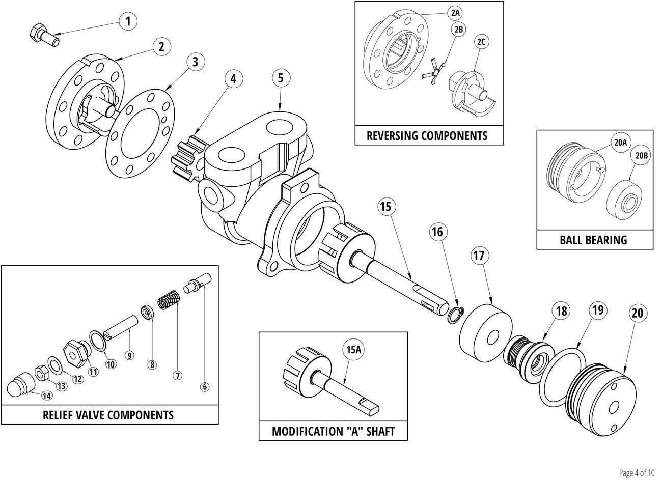
Utilizing detailed and precise visual representations of mechanical systems offers a multitude of advantages, especially when dealing with complex machinery. These illustrations serve as essential tools for understanding the intricate design and functionality of components, ensuring effective maintenance, repair, and optimization. When accuracy is prioritized, it minimizes errors and improves the overall efficiency of system operations.
Enhanced Troubleshooting and Maintenance
When systems are depicted clearly and accurately, identifying and diagnosing issues becomes significantly easier. Technicians can quickly locate the source of problems, reducing downtime and the need for unnecessary disassembly. This not only saves time but also prevents costly mistakes that could arise from misinterpretation of the system’s layout.
Improved Efficiency and Performance
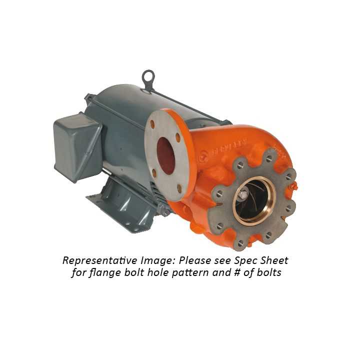
With precise schematics, adjustments and upgrades can be made with confidence, allowing for optimal configuration. This leads to improved efficiency, as every element is designed to function harmoniously. Accurate documentation also facilitates training for new operators, ensuring a smoother workflow and better system performance overall.
Exploring Different Berkeley Pump Models
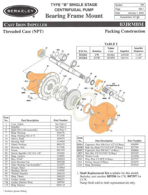
When it comes to high-performance water-moving systems, a wide variety of models are available, each offering unique features and capabilities. Understanding the differences between these models is essential for selecting the right equipment to meet specific operational needs. From standard versions designed for everyday tasks to advanced variants for specialized applications, each model is engineered with distinct components to optimize efficiency and output. In this section, we will explore the range of available models, highlighting key distinctions in design and function.
| Model | Application | Capacity | Key Features |
|---|---|---|---|
| Model A | Residential Use | Up to 500 GPM | Durable construction, easy maintenance, low energy consumption |
| Model B | Agricultural Irrigation | Up to 1000 GPM | High efficiency, robust performance in challenging conditions |
| Model C | Commercial and Industrial | Up to 2000 GPM | Enhanced flow rate, customizable components for varied uses |
| Model D | Marine & Recreational | Up to 300 GPM | Corrosion-resistant materials, compact and portable |
Each system is designed to tackle different challenges effectively. Whether it’s the high-capacity units for industrial sectors or smaller, portable models for recreational use, selecting the right model ensures optimal performance and longevity. The key lies in understanding the specific requirements of your project and matching them with the appropriate system configuration.